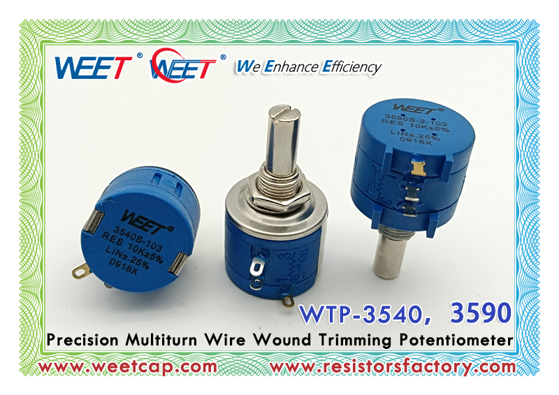
WEET WTP 3590 Rotary Metal Wire Wound Precision Trimming Potentiometer
WEE Technology Company Limited - Manufacturer For Full Range of Resistors
A. Debugging method for multi turn precision adjustable potentiometer
1. Correct connection of input signal source
First, connect the signal wire of the input signal source to the middle pin of the potentiometer, and then connect the output end to the load.
2. Resistance adjustment of potentiometer
When debugging a circuit, the resistance of the potentiometer should be adjusted to a smaller value first. Once the resistance value is determined, it can be gradually increased.
3. Offset calibration of potentiometers
When using a potentiometer, there may be unstable situations where the potentiometer drops or rises, and offset calibration is required.
B. Precautions for multi turn precision adjustable potentiometers
1. Multi turn precision adjustable potentiometers should avoid exceeding the rated voltage and current.
When debugging the circuit, attention should be paid to the polarity and wiring of the power supply to avoid short circuits and power damage.
During the debugging process, the sliding trajectory of the potentiometer may cause wear and tear, and attention should be paid to protection.

