Resistors are widely used, but different applications require different types of resistors. Do you know the differences between radial and axial resistors?
Let WEET tell you, the core difference between radial and axial resistors lies in their lead arrangement and application scenarios.
INTRODUCTION
Resistors Types
Through hole resistor: Leads extend from both ends of the resistor body along the central axis.
Radial resistor: Leads protrude from the same end (or adjacent positions) of the body.
Mounting Method and Space Occupation
Through hole resistor: Axial resistor sizes for through-hole mounting, requiring linear space reserved along the direction of the leads.
Radial resistors: Support through-hole mounting and surface mount technology (SMD). Vertical mounting saves horizontal space, enabling a more compact layout.
Application Scenarios
Through hole resistor: Commonly used in traditional circuits, audio equipment, and projects with fixed requirements for lead spacing.
Radial resistors: Preferred for miniaturized devices such as printed circuit boards (PCBs) and high-density circuits.
https://www.resistorsfactory.com/Axial-Resistors/
Contact us: Sales@weetcap.com

WEE Technology Published on Nov 18, 2025
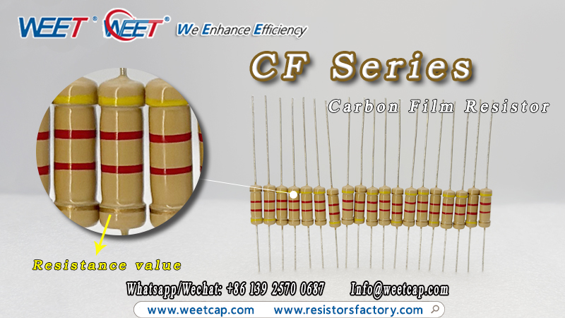
As one of the most basic components in electronic circuits, a resistor exerts a certain hindrance to the flow of electric current. But do you know how to read carbon film resistor color code?
These colorful bands actually indicate the resistor's resistance value - a detail that can be confusing for many beginners. However, with WEET guidance, you'll surely learn to identify the resistance value quickly.
First, carbon film resistor is generally classified into 4-band resistors and 5-band resistors based on the number of color bands.
Start by memorizing this mnemonic:
Brown=1, Red=2, Orange=3, Yellow=4, Green=5, Blue=6, Violet=7, Gray=8, White=9, Black=0.
Resistance value:
Gold=±5%, Silver=±10%.
Take the CF Series 4-band resistors in the figure below as an example:
1st digit: Yellow=4
2nd digit: Red=2
Multiplier: 2×100
Tolerance: ±5%
So, the resistance value of this resistor is 4K2 Ω.
After this explanation, you must have a general understanding. Feel free to contact WEET if you need carbon film resistor!
More information:WEET CF Series Carbon Film Resistor-Axial Resistors-WEET Resistors | China MF CF MOX KNP Resistors Factory-
Contact us:Sales@weetcap.com
WEE Technology Published on Nov 14, 2025
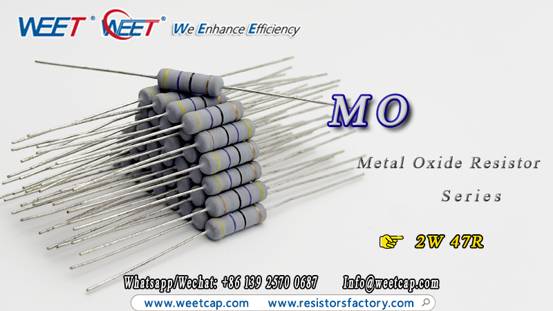
Through hole resistors are hidden in various electrical devices and play a huge role, so have you ever wondered about their size?
Next, I will elaborate on several features related to through hole resistors MO.
Features:
Operating Temp. Range: -55℃~ +155℃
Wide Resistance range: 1Ω~180KΩ
Standard tolerance: ±1%, ±2%, ±5%
Temp. Coefficient (by Type): ±350ppm/℃
Dimension(mm):
Series: MO 2W 47R
L: 15±0.5mm
ØD: 5.0±0.5mm
H: 32±2mm
Ød: 0.78±0.05mm
Click the link for more information about through hole resistors:
WEET-MO-Sereis-Metal-Oxide-Resistor
Contact us:Sales@weetcap.com
WEE Technology Published on Nov 13, 2025
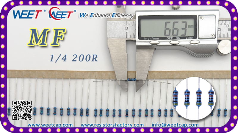
Do you know how to choose an axial leaded resistor that suits you?
Here are a few suggestions from WEET.
Resistance Value and Tolerance
Determine the required resistance value (typically ranging from a few ohms to several megaohms) based on the circuit design requirements. Choose an appropriate tolerance grade according to the precision needs.
Rated Power
Select the rated power based on the actual power consumption in the circuit. It is recommended to reserve a 20%~30% power margin to prevent overheating damage caused by the axial leaded resistor operating at full load for a long time.
Temperature Coefficient (TCR)
It indicates the degree to which the axial leaded resistor's resistance changes with temperature. For precision scenarios (such as medical equipment and test instruments), select low-TCR models (e.g., ±10ppm/℃ or lower). For general scenarios, the requirement can be relaxed to ±100ppm/℃.
Package Size
Choose a suitable body size based on the circuit board's spatial layout. Ensure the pin spacing matches the pad spacing of the circuit board to facilitate soldering and installation.
Contact us: Sales@weetcap.com
Click the image to view the PDF.
WEE Technology Published on Nov 12, 2025
Where can we buy axial resistor at a great price online? Definitely from China's WEET factory! We provide you with the best experience throughout, whether it's product quality or after-sales service.
Now, let WEET introduce our product: 1W 1K OHM CF Series Axial Resistor.
FEATURES:
Operating Temp. Range: -55℃~ +155℃.
Tolerance Specifications: Standard tolerance of ±2% and ±5%.
Stability: Exceptional long-term stability, exceeding the performance standards of MIL-R-11 carbon composition resistors.
Packaging Options: Flexible packaging solutions available, including bulk, strip pack, 26mm tape and reel, and 52mm tape and reel.
APPLICATIONS:
Industrial Control Equipment.
Consumer Electronics.
Automotive Electronics.
Telecommunications Equipment.
Medical Devices.
Power Supply Units.
More Details:https://www.resistorsfactory.com/Axial-Resistors/WEET-CF-Series-Carbon-Film-Resistor.html
More Informations:https://www.resistorsfactory.com/Applications/WEET-Resistors-in-Automotive-Applications.html
If you need axial resistor, feel free to contact us!
Contact Information:Sales@weetcap.com

WEE Technology Published on Nov 11, 2025
The polarized axial aluminum electrolytic capacitor is a high-performance capacitor that is indispensable for the operation of numerous devices.
But, do you know where WAA 500V polarized capacitor axial leaded is used?
INTRODUCTION
The application scenarios of 500V polarized capacitor axial leaded cover multiple mainstream electronic fields,
being compatible with various core devices and components.
In the communication field, they are widely used in power supplies and mainboards of communication products,
and also serve as key supporting components for frequency converters and various power supply equipment.In audio-related fields, they can be adapted to audio devices, frequency dividers,
and audio amplifiers to ensure stable sound quality transmission.For display equipment, they are applicable to LCD displays, LCD TVs (with dedicated models),
and electronic digital photo frames, facilitating smooth display output.In addition, they are also suitable for daily and professional electronic devices such as energy-saving lamps,ballasts,
and cameras, and play an important role in the automotive electronics field,
providing crucial support for the stable operation of various electronic devices.
SUMMARY
WEET WAA 500V polarized capacitor axial leaded offer free samples. For requests, feel free to contact our sales team anytime!
Details:WEET-WAA-AXIAL-85C-2000H-Polarized-Aluminum-Electrolytic-Capacitors-Standard-High-Voltage
Contact us:Sales@weetcap.com

WEE Technology Published on Oct 31, 2025
Beyond its well-known role in audio systems, what other functions of 500V axial leaded capacitors?
Let me break it down briefly for you. For full details, just click the link below!
1. Industrial Electronics & Control
Industrial Power Modules: Ideal for frequency converters.
Motor Control Circuits.
Precision Instruments & Meters.
2. Audio & AV Equipment
Retro Audio Gear.
Professional Audio Setups: Think the power sections of mixers and recording devices.
3. Automotive Electronics
In-Vehicle Power Systems: Perfect for on-board inverters and chargers.
Automotive Control Systems.
4. Medical & Security Equipment
Medical Devices: Such as the power circuits in ECG machines and blood pressure monitors.
Security Surveillance Systems.
CONCLUSION
8uF 16uF WAA 500V axial leaded capacitors are polarized. It boast an incredibly wide range of applications. And to meet the demands of high-performance machinery and equipment, we've even upgraded them to a 500V high-voltage rating - just for you.
Ready to learn more about how they fit your project? Click the link now, or reach out to our team for personalized support!
WEET WAA Axial 85C 2000H Polarized Aluminum Electrolytic Capacitors Standard High Voltage
Contact us: Sales@weetcap.com

WEE Technology Published on Oct 30, 2025
Are you looking for WAA 500V axial polarized capacitors? WEET Supply Them!
First, let me give a basic introduction to it.
INTRODUCTION
WAA 500V axial polarized capacitors is an aluminum electrolytic capacitor with two metal leads drawn out from both ends of the cylindrical case, and it has clear positive and negative polarities.
Specifications
Life: 2000hours
Capacitance: 70uF 500V
Operating Temperature Rang (℃): -40℃ ~+85℃
Capacitance Tolerance (20℃, 120Hz): ±10% (K), ±20%(M)
Voltage Range: 6.3 ~ 160VDC, 160 ~ 450VDC
CONCLUSION
WEET offer high quality axial polarized capacitors WAA. In response to customer needs, we have specifically upgraded our WAA axial polarized aluminum electrolytic capacitors to 500V.
Still hesitating? We can send free samples.
PDF: WEET-WAA-AXIAL-85C-2000H-Polarized-Aluminum-Electrolytic-Capacitors-Standard-Low-Voltage
Contact us:Sales@weetcap.com

WEE Technology Published on Oct 29, 2025
It is presumed that everyone must have encountered a question in daily life: how to identify an axial polarized electrolytic capacitor - WAA.
INTRODUCTION
The core method to identify an axial polarized electrolytic capacitor is to observe its case polarity markings, which is the most direct and standardized way of judgment.
1. Identify the Negative Terminal (-) Markings on the Case
Color Band Marking: A continuous color band is printed around one end of the metal case. The lead corresponding to this color band or the electrode at that end is the negative terminal (-). This is the most commonly used negative marking method in the industry, and WEET WAA also follows this practice.
"-" Symbol Marking: Some capacitors have the "-" symbol printed on the side of the case.
Text Marking: A very small number of models are directly marked with "Negative" or its abbreviation "Neg".
2. Auxiliary Judgment by Appearance
Package Type: Mainly cylindrical metal cases.
Common Lead Configurations: There are two common lead configurations: radial leads and axial leads.
SUMMARY
Axial polarized electrolytic capacitors are easy to distinguish; you only need to carefully observe their appearance.
At the same time, if you need free samples for testing, please contact us.
More Details: WEET WAA Axial 85C 2000H Polarized Aluminum Electrolytic Capacitors Standard Low Voltage
Contact us:Sales@weetcap.com

WEE Technology Published on Oct 28, 2025
To keep pace with the evolving times, WEET has now developed a new type of capacitor called the Lug Type Aluminum Electrolytic Capacitors.
Compared with traditional lead-type capacitors, the lug type capacitor is directly soldered onto the PCB. This design provides a larger contact area and eliminates the risk of lead breakage.
INTRODUCTION
Next, let WEET introduce two different series of Lug Type Aluminum Electrolytic Capacitors, WEG and WEH. The WEG model also comes in a pin-type version.
WEG Series
Operating Temperature Range (℃): - 20℃ ~ +55℃
Rated Voltage: 330V~450V
Capacitance Tolerance: -10%~20%(20℃,120Hz)
Main Application: For photo flash
Cross to Nichicon 180uf 315v photo flash capacitors Low ESR
WEH Series
Operation Temperature Range (℃): -40~+85℃ | -25~+85℃
Rated Voltage: -40~+85℃: 10~100VDC | 160~450VDC
Capacitance Tolerance: ±20%(120Hz,20℃)
Main Application: For power supply input filter | TV sets
SUMMARY:
WEET Lug Type Aluminum Electrolytic Capacitors are compact, lightweight, and small in size. If you need free samples for testing, please feel free to contact us at any time.
Details:WEET-WEG-Lug-Aluminum-Electrolytic-Capacitors-For-Photo-Flash
WEET-WEH-85C-2000H-Lug-Aluminum-Electrolytic-Capacitors
Contact us:Sales@weetcap.com

WEE Technology Published on Oct 27, 2025